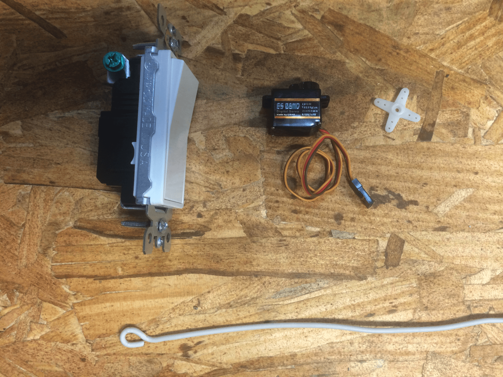
Materials
| Qty | Description | Link |
|---|---|---|
| 1 | Decora Light switch | Home Depot |
| 1 | 9g servo (preferably with metal gears) | Amazon | EBay |
| a few inches | 14 guage wire | Scrap romex |
Tools
| Description |
|---|
| Dremel |
| Needle nose pilers |
| Hot glue gun |
| Thin blade flat head screwdriver |
Step 1
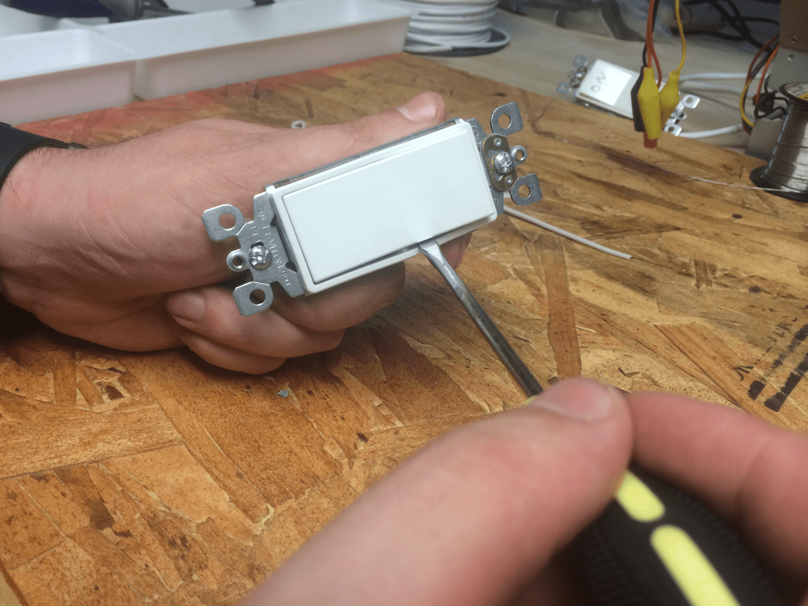
Gently pry the lightswitch paddle off.
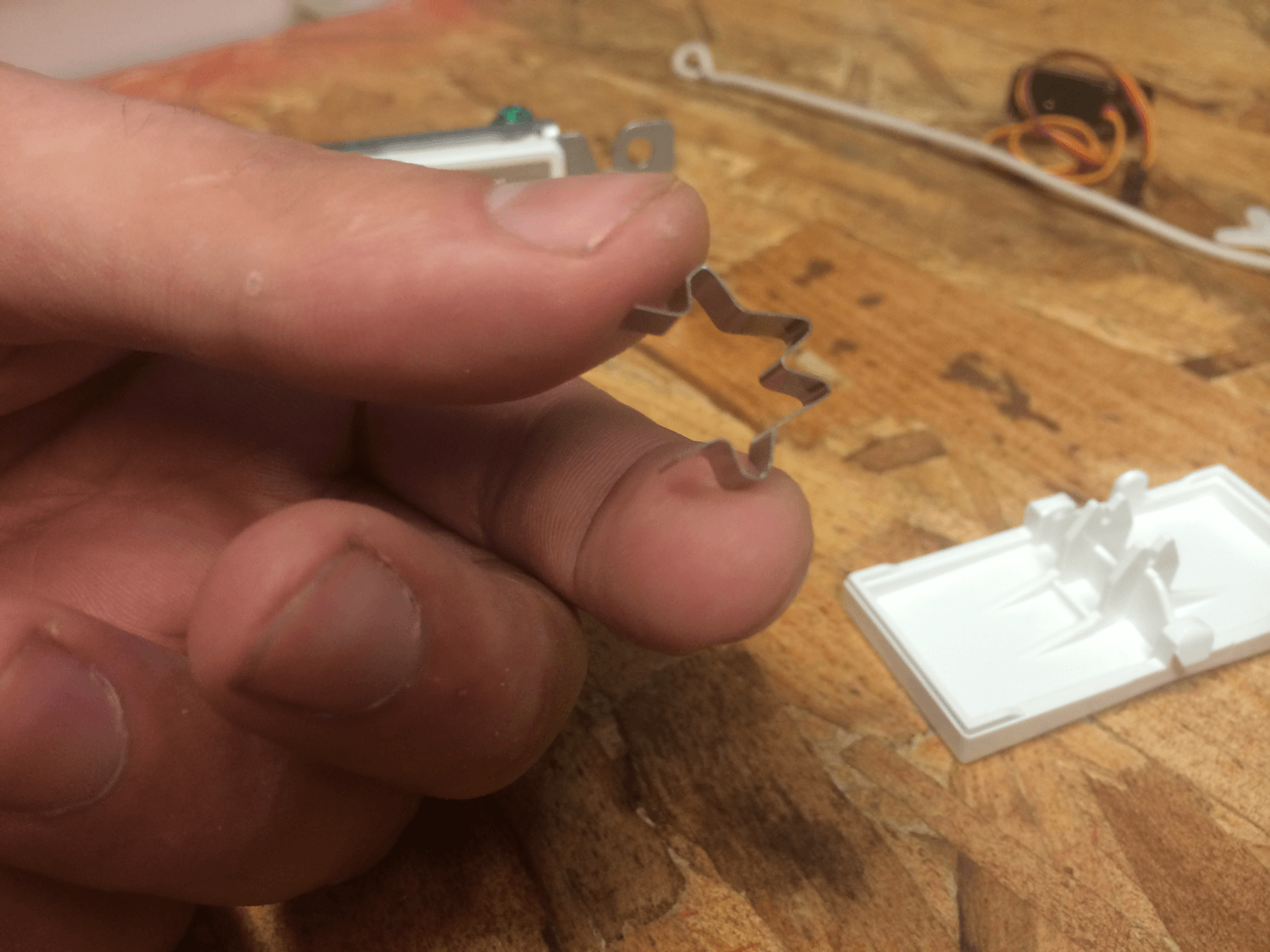
Careful not to loose this little piece of metal
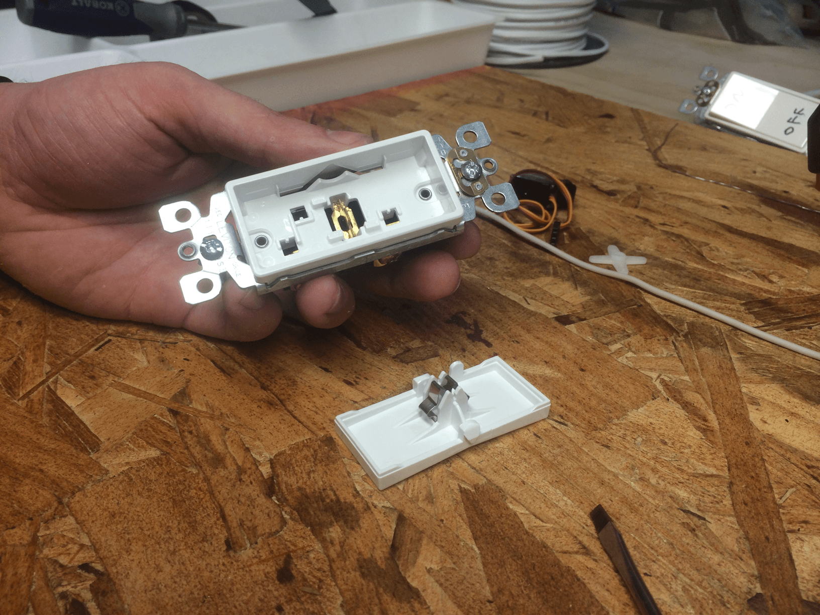
Final Result
Step 2
Measure out some wire
And give it a bend
And another bend
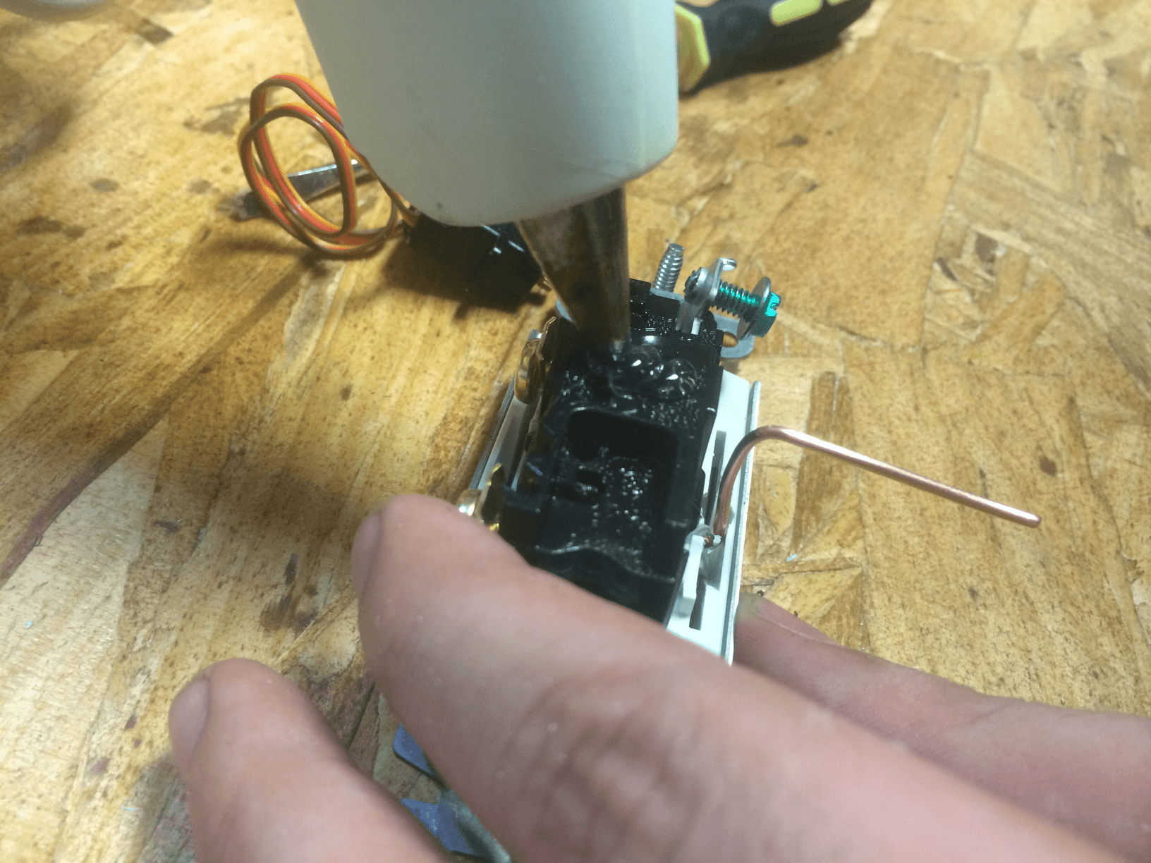
Strip the tip of the short side up to the plastic block
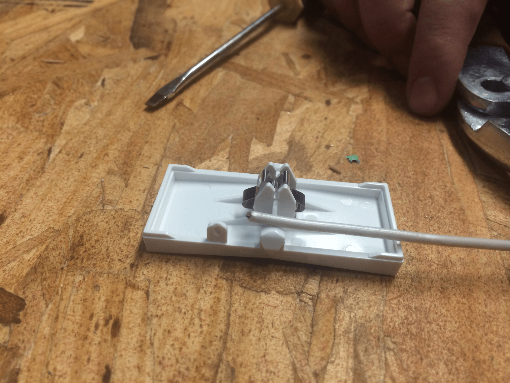
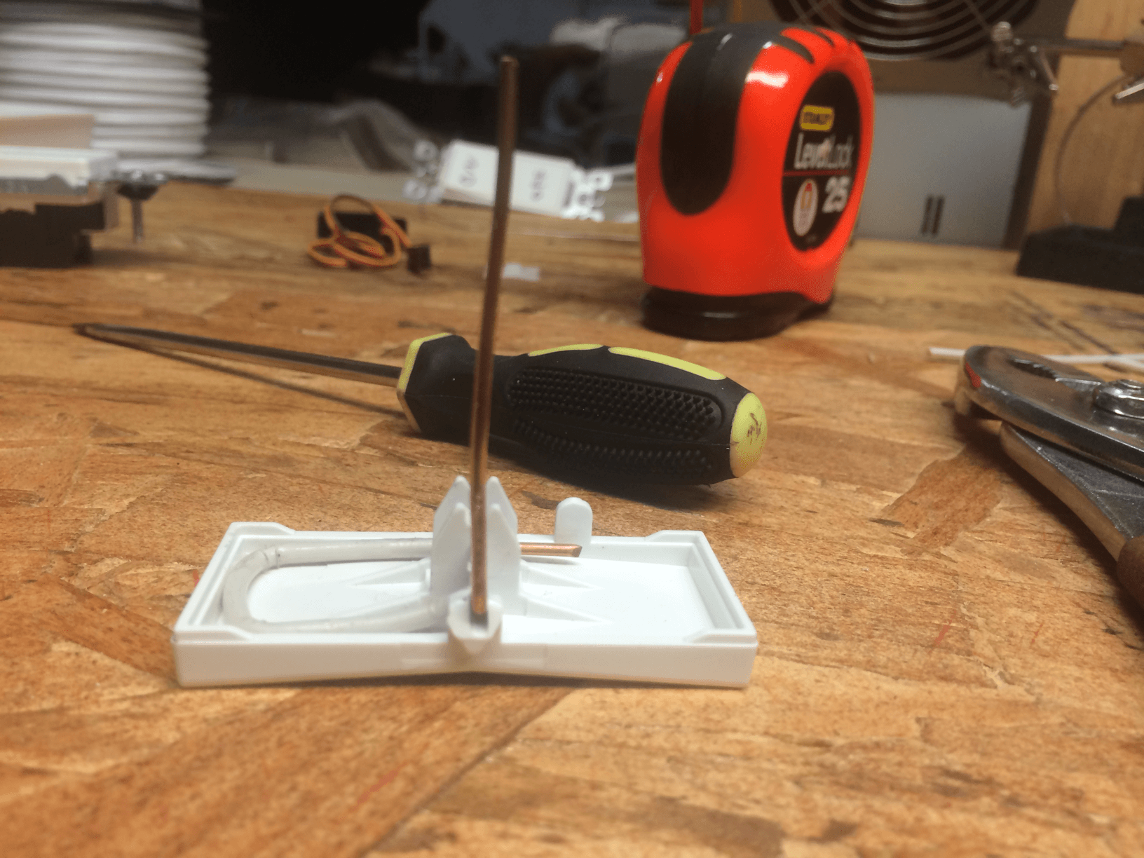
Drill a small hole through the plastic block to allow the stripped wire to pass through
Make sure the wire fits snugly inside of the paddle
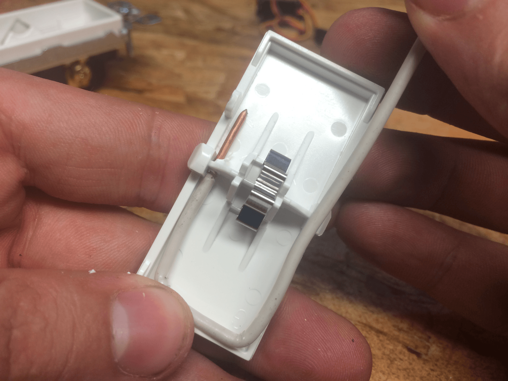
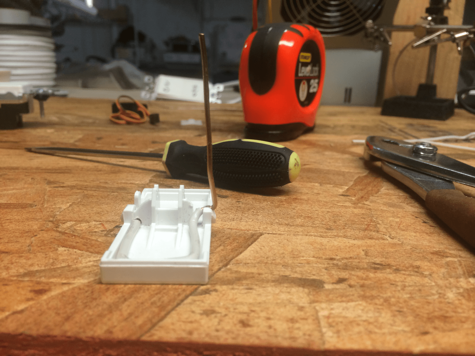
Dremel out a valley on the opposite side of your drill hole
After and before
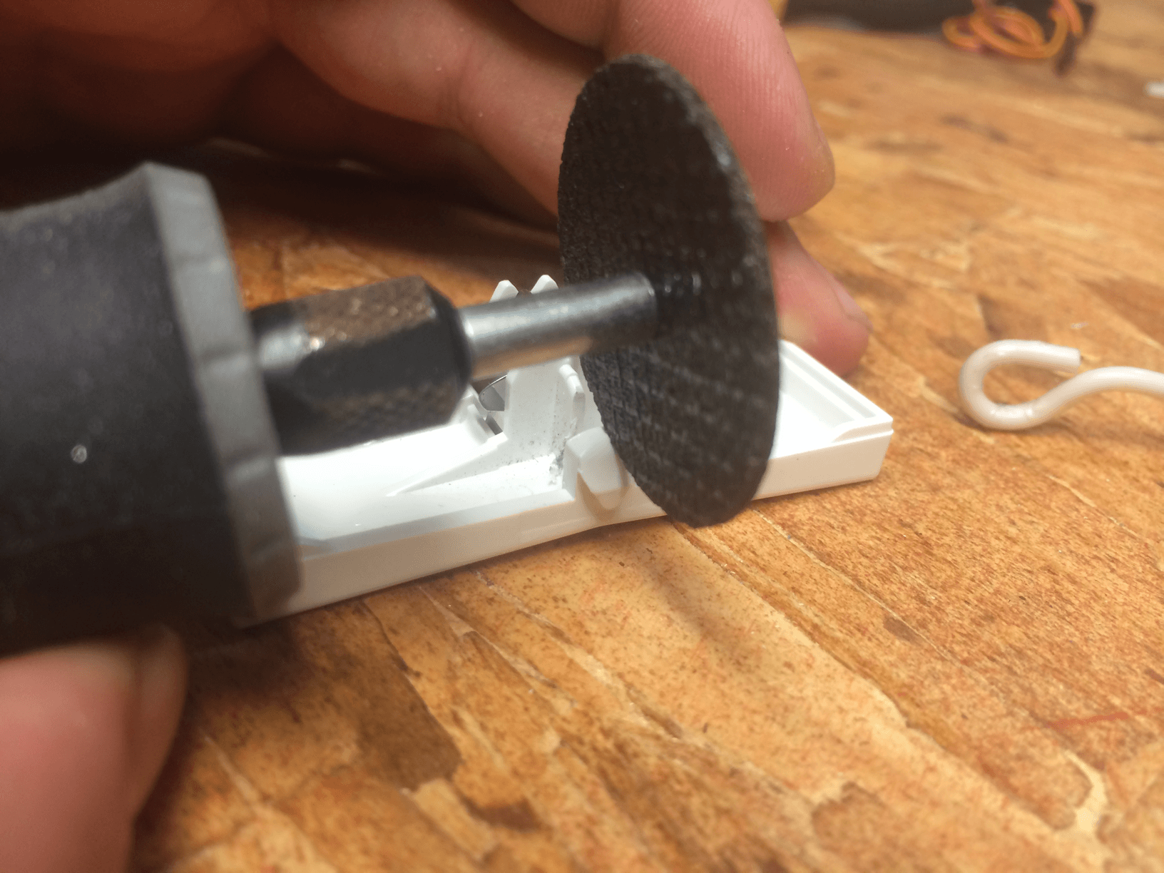
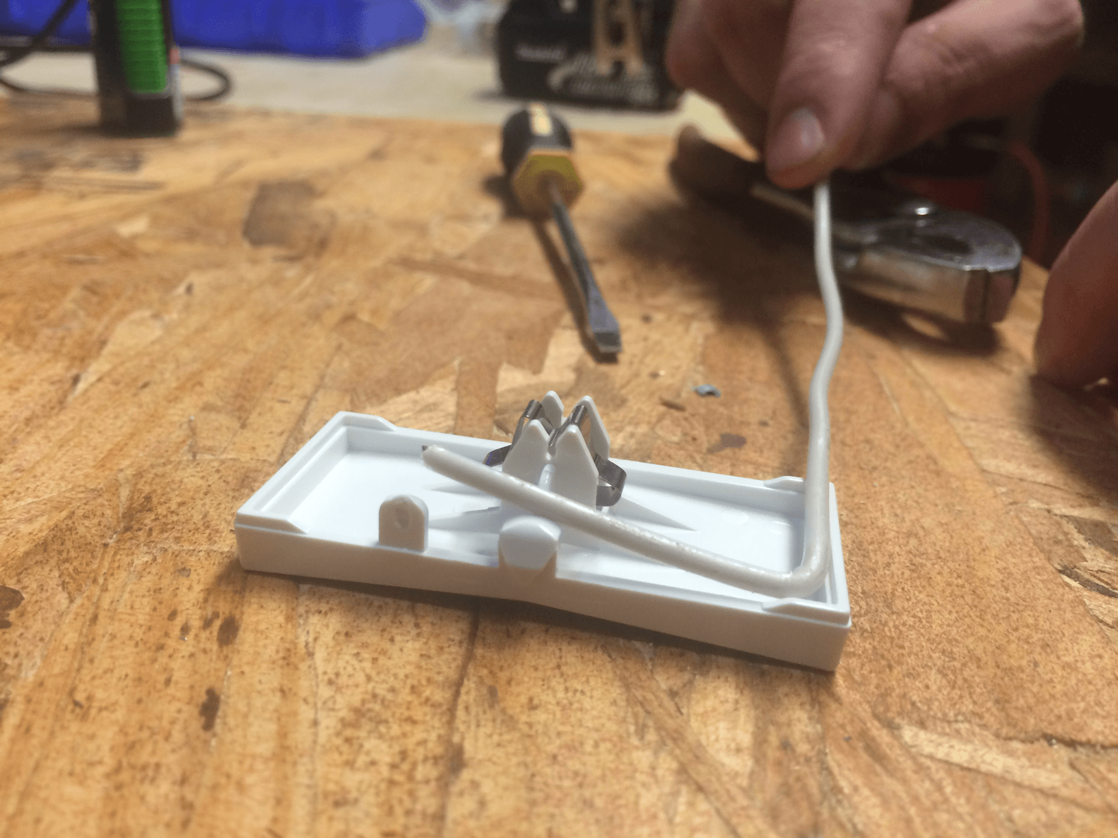
Notch out a valley on the outer part of the plastic clip big enough for a stripped bit of wire to fit into
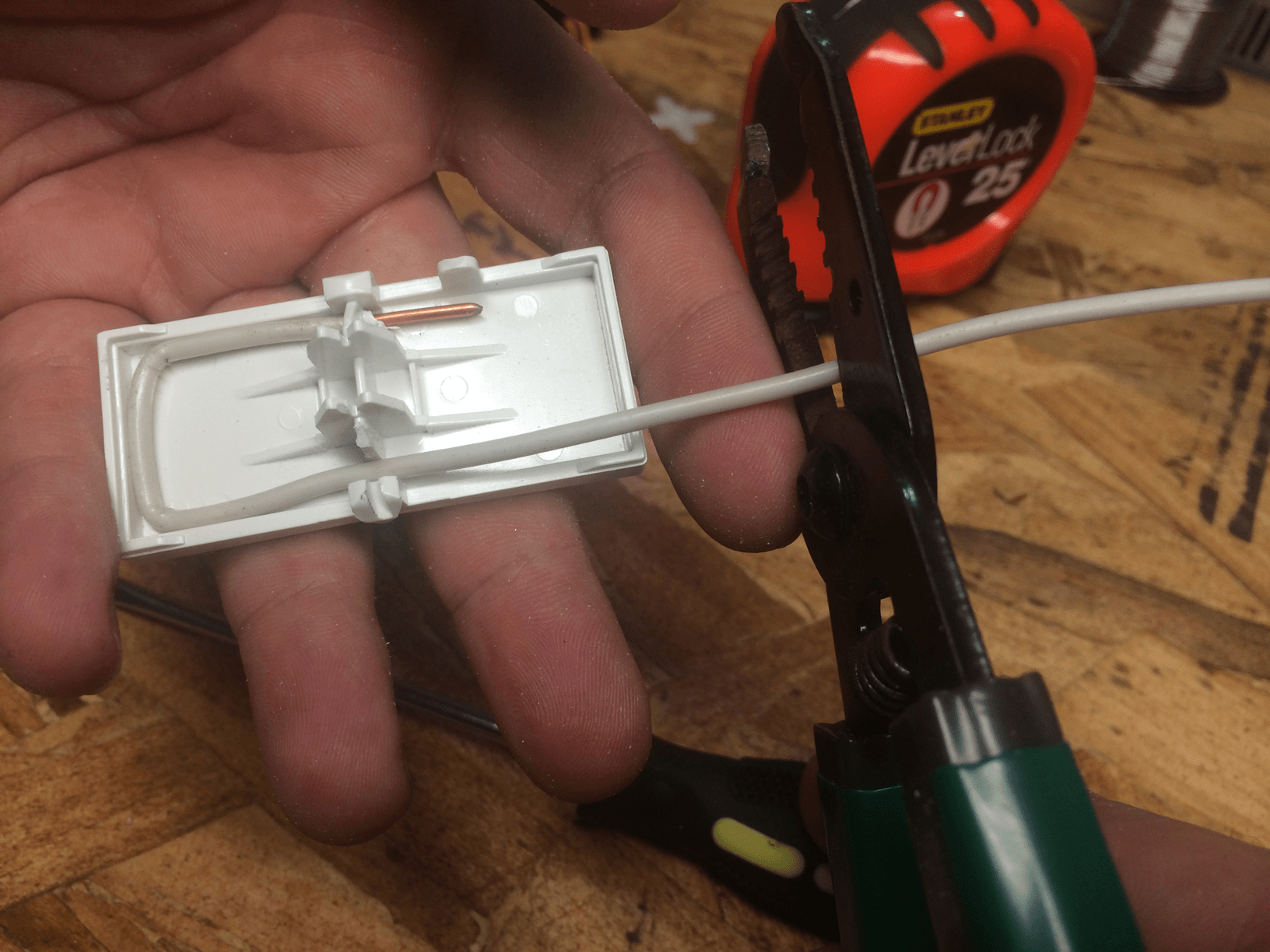
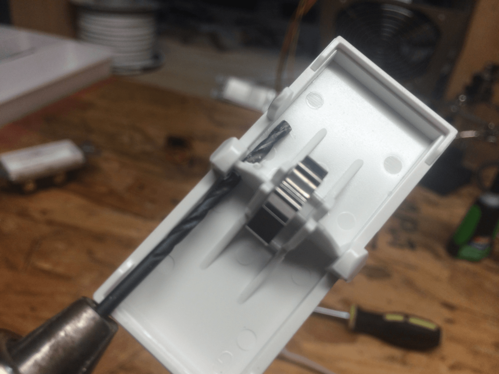
Cut the long side of the wire about an inch past the paddle’s length
And strip back until the middle of the paddle
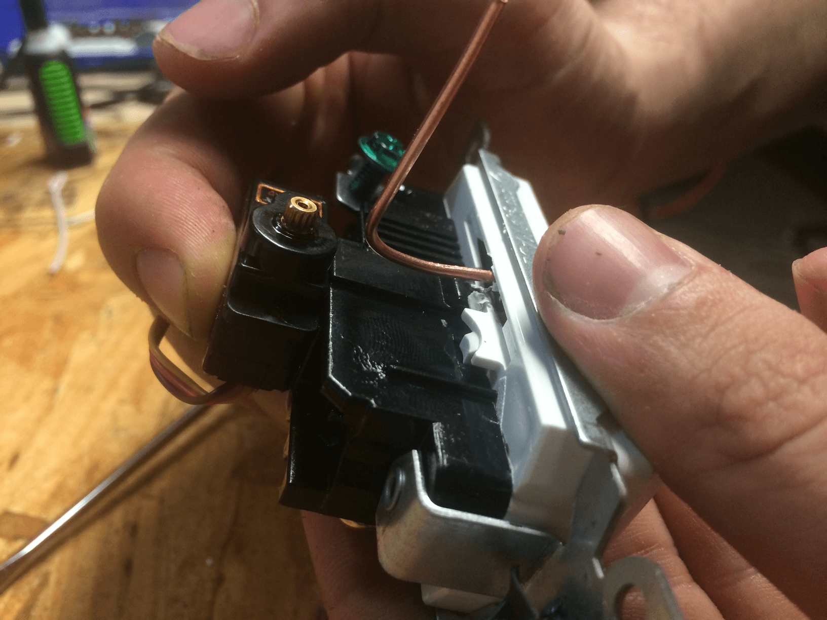
Fit the wire into the valley you notched out
And bend it upwards so that it is flush to the outside.
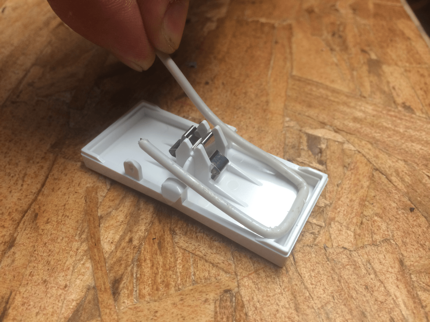
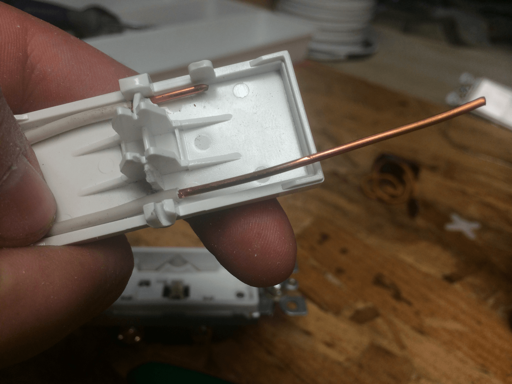
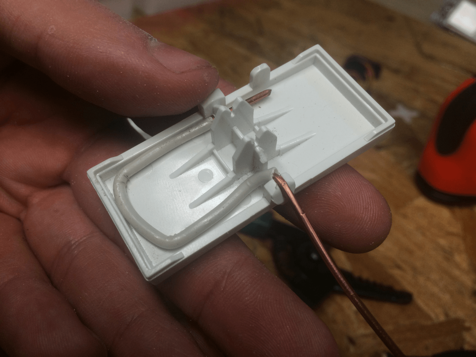
Here is another view of the prior step.
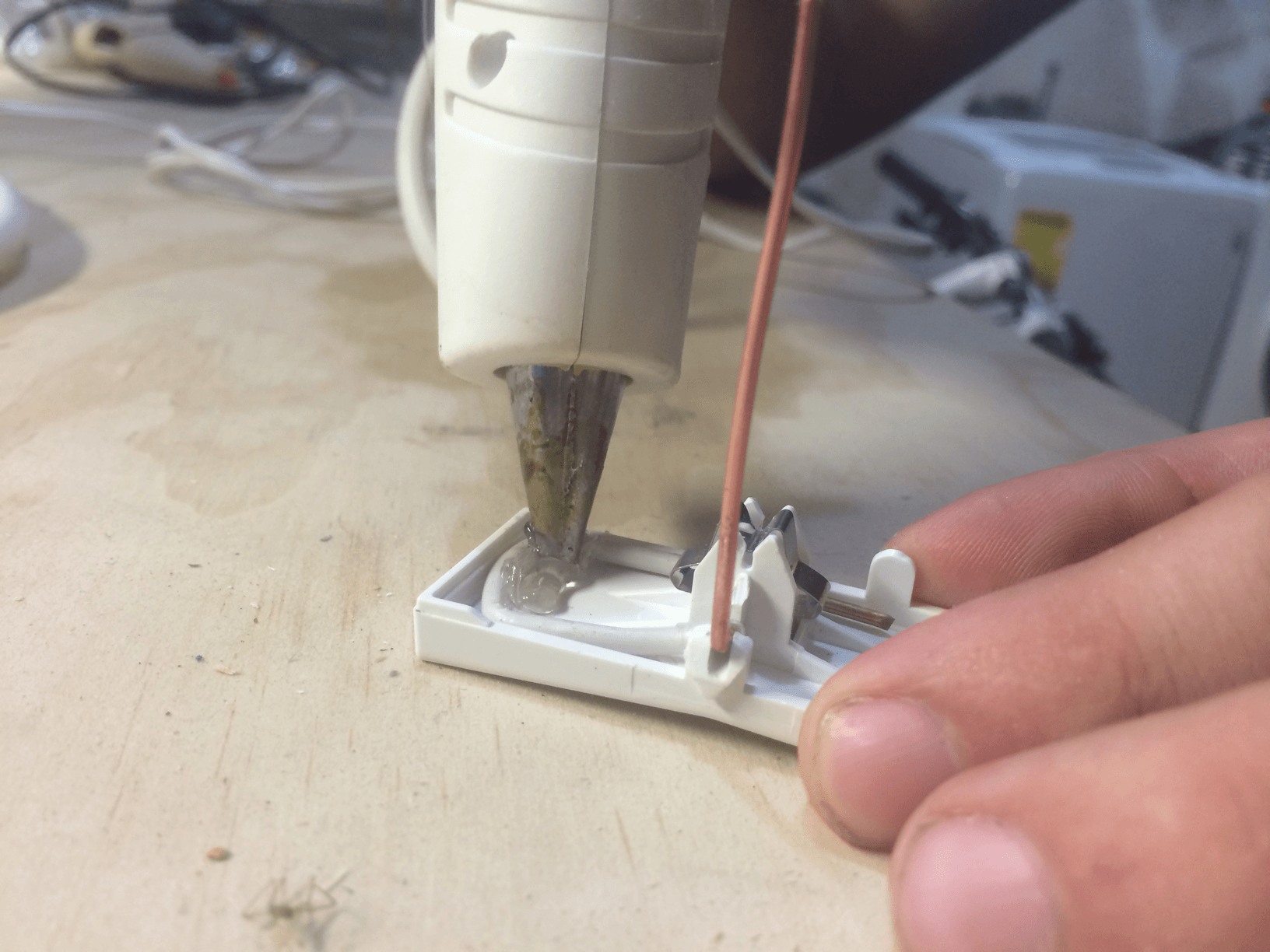
Hot glue down your handywork
Step 3
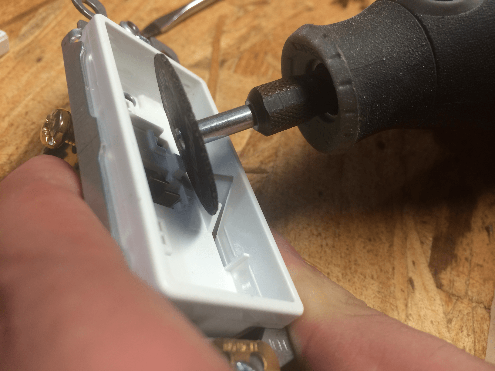
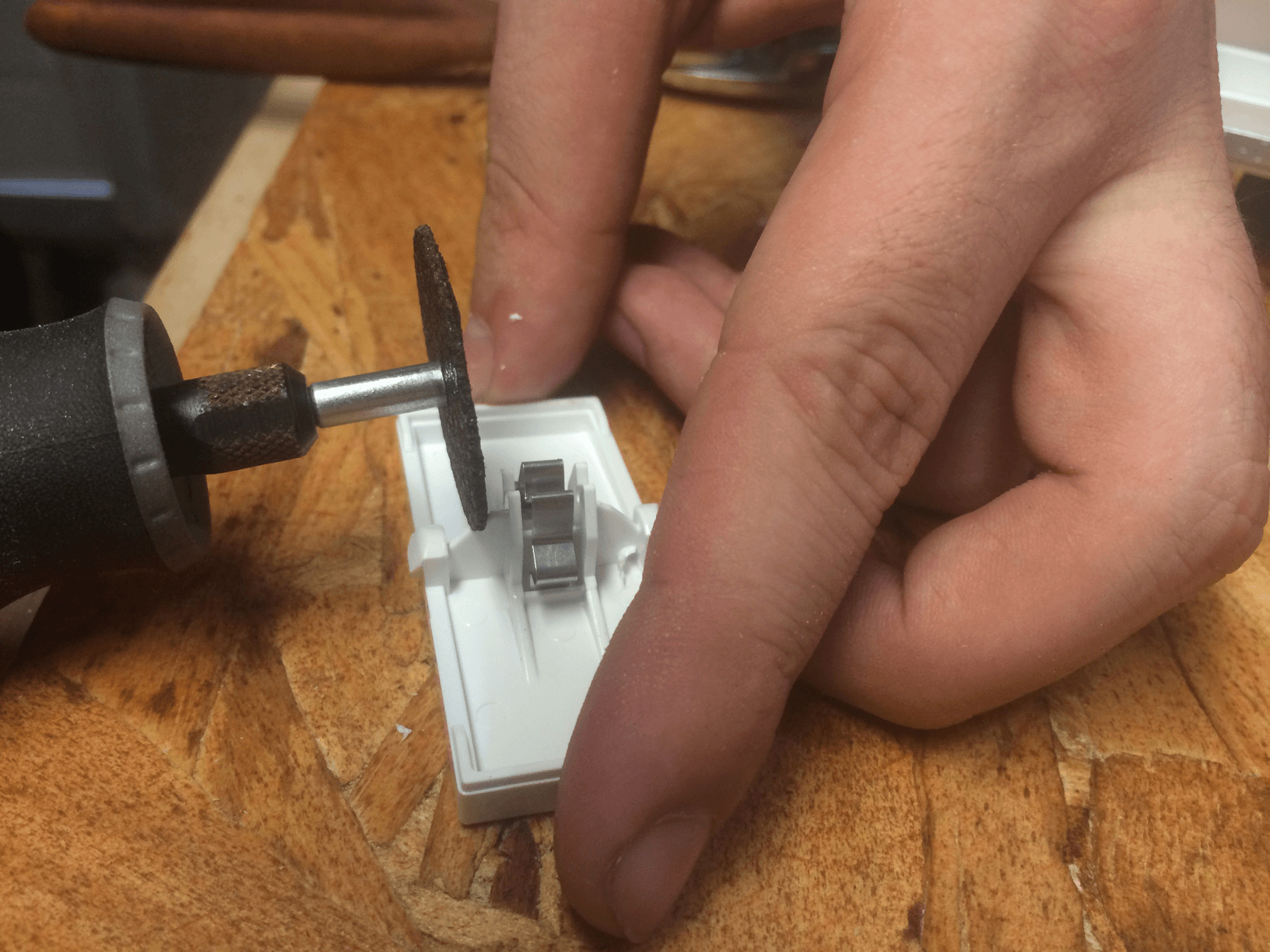
Remove the tab on the opposite side of the screw terminals
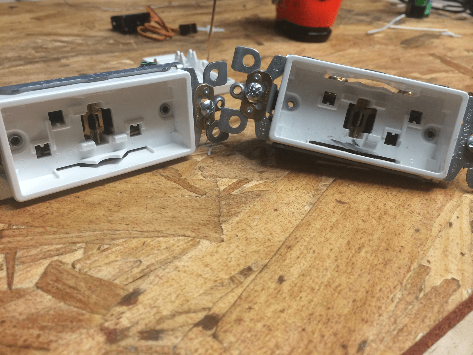
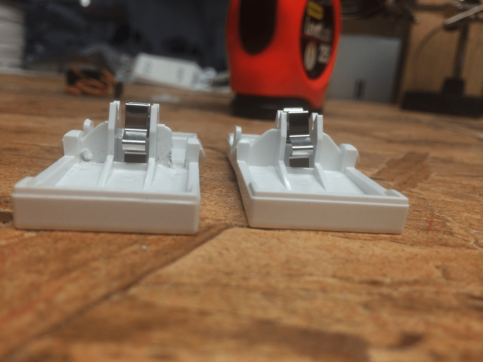
Before and after
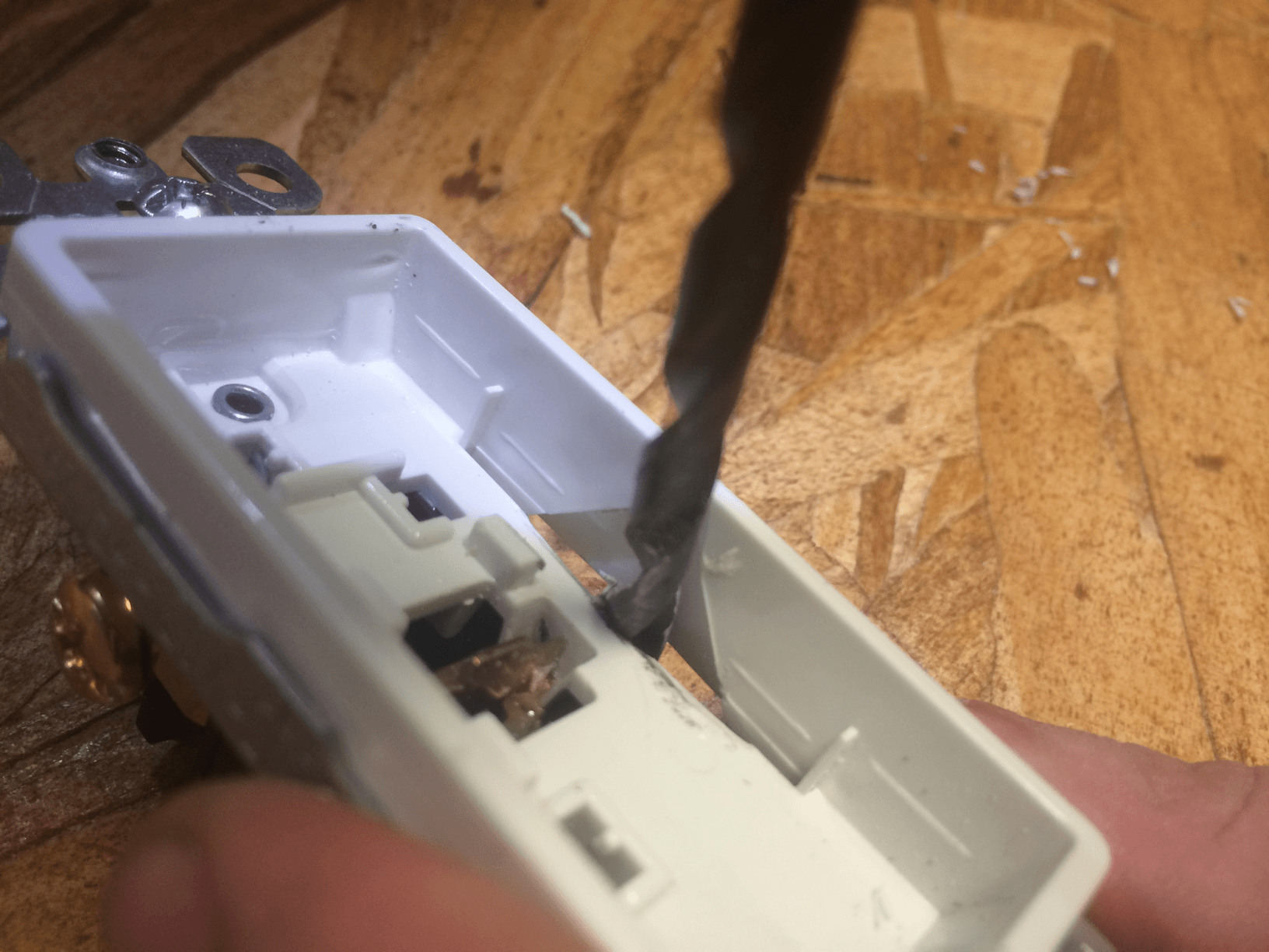
Drill a 1/4in hole down the middle of the tab you just removed
Snap it together, and make sure it toggles with ease
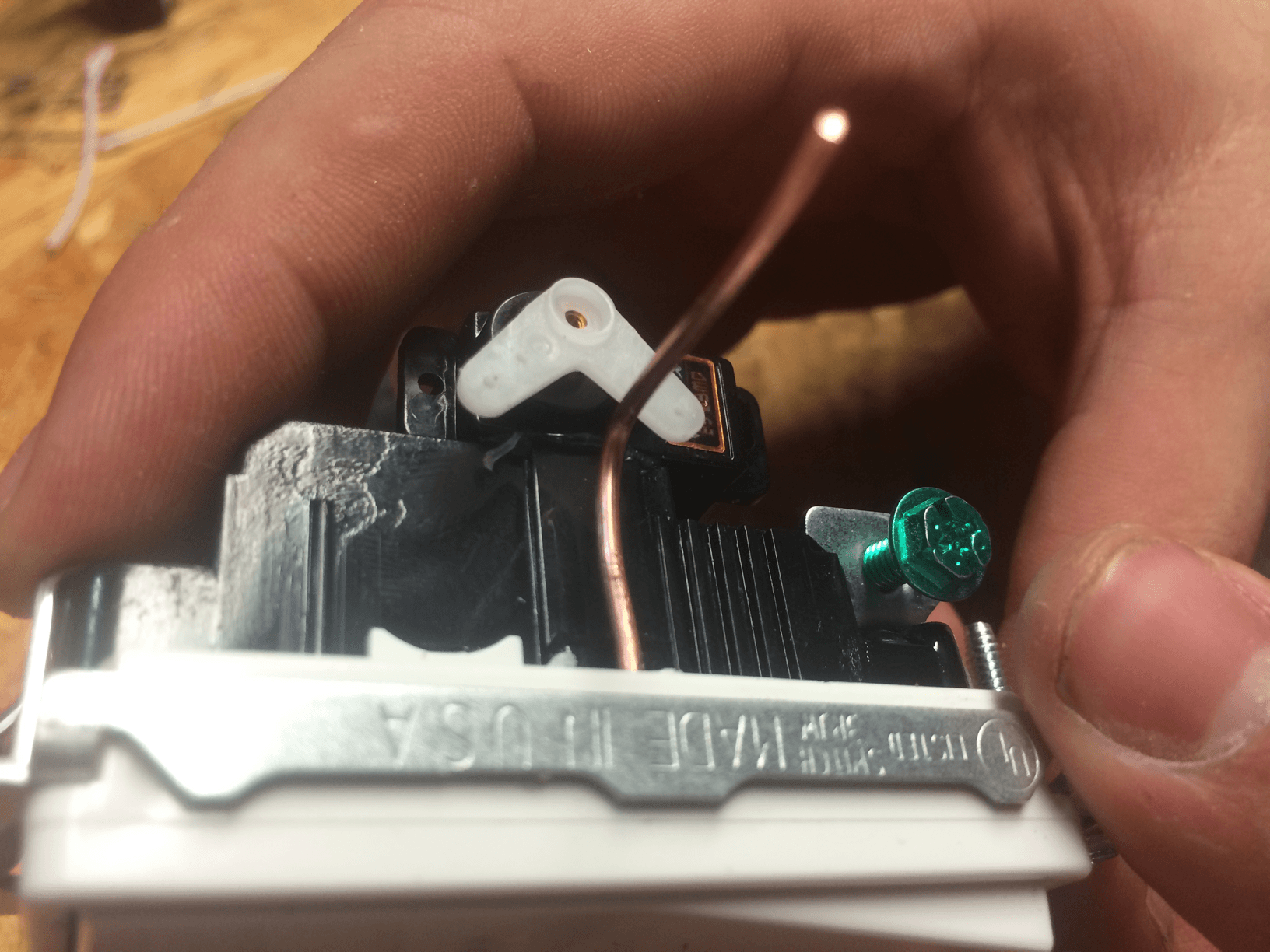
Step 4
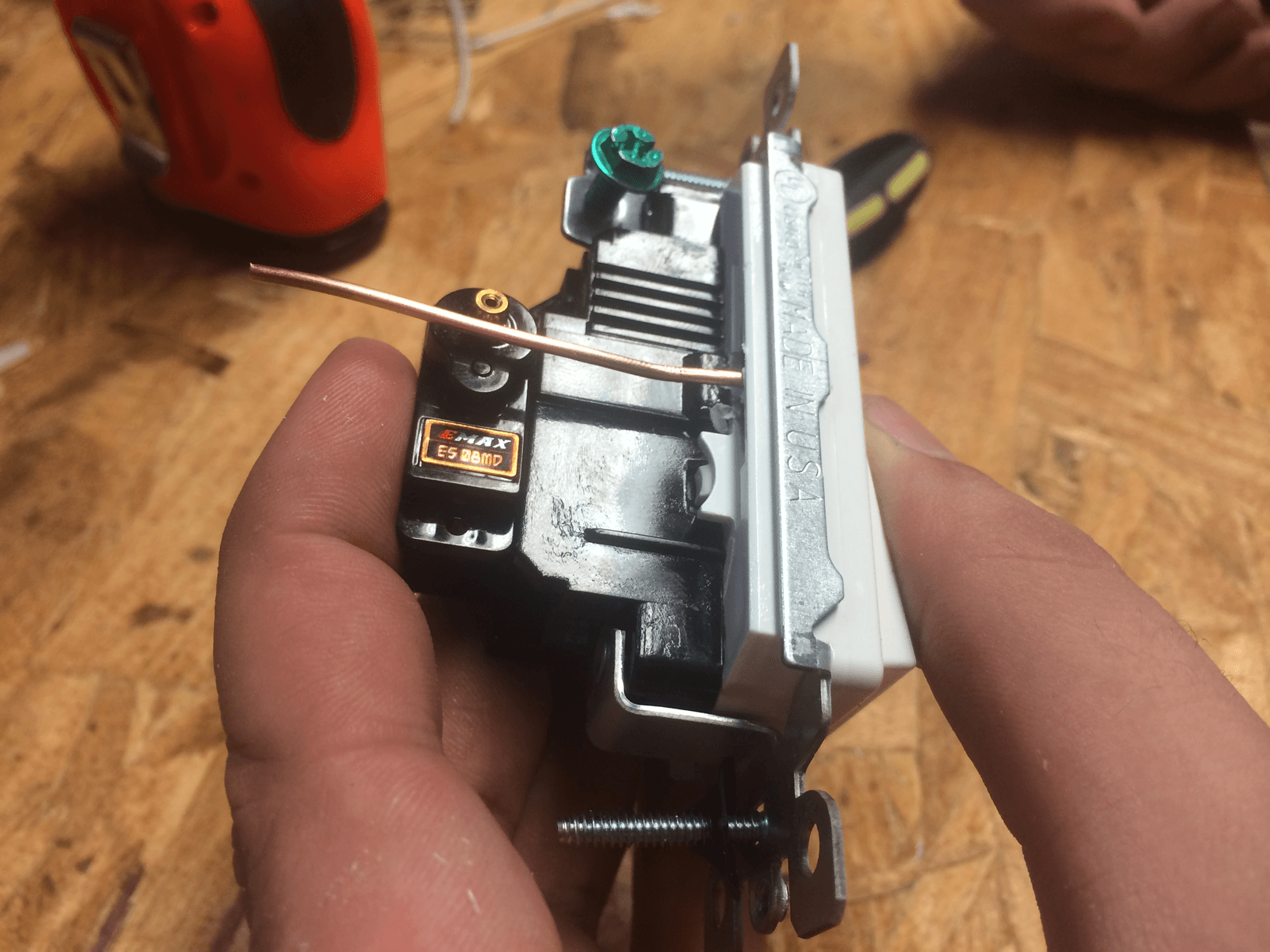
Position the servo so that it is flush to the switch body

Make sure not to cover this hole

Or this one
Hot glue down your handywork
Final product
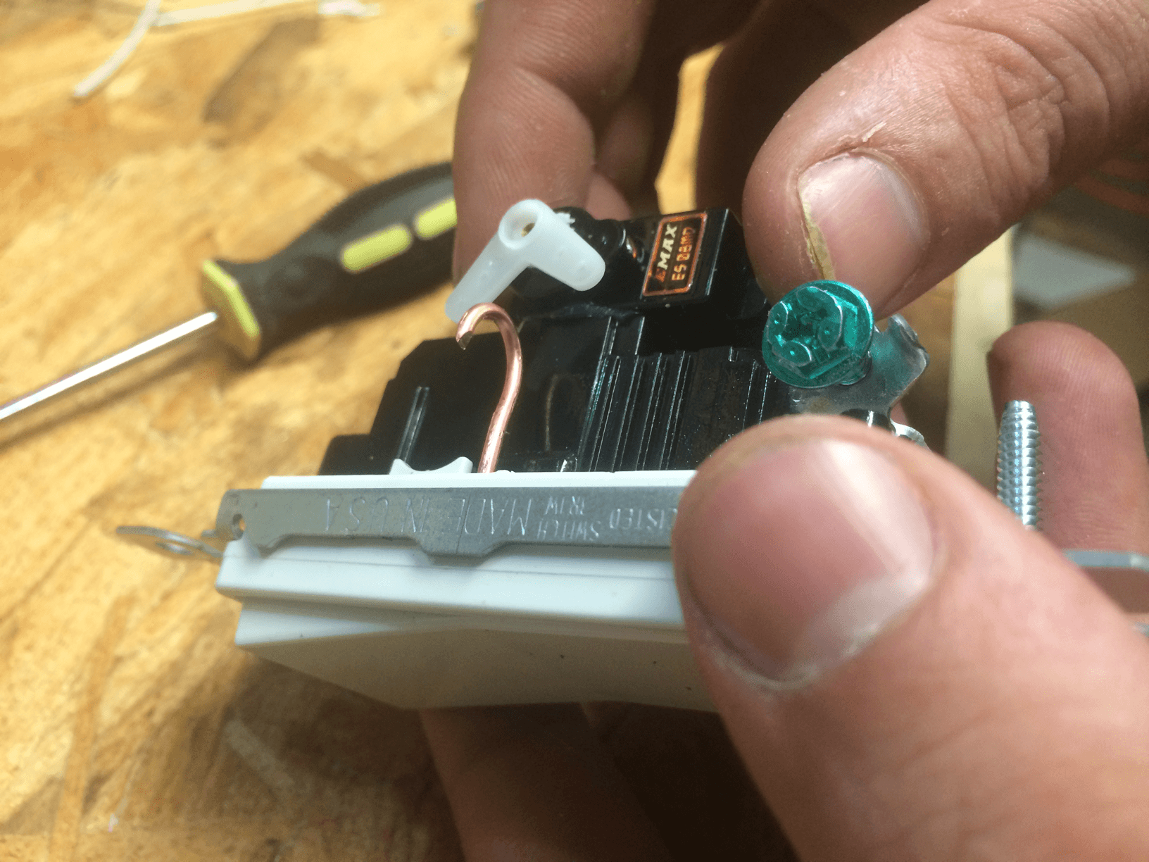
Step 5
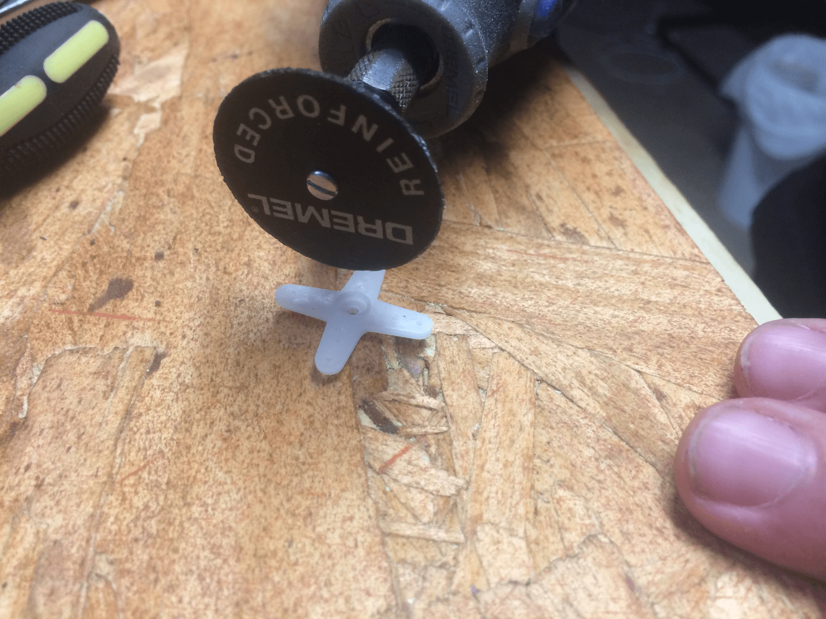
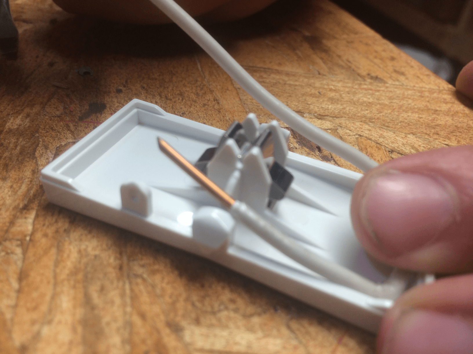
Chop two legs off of a X servo horn
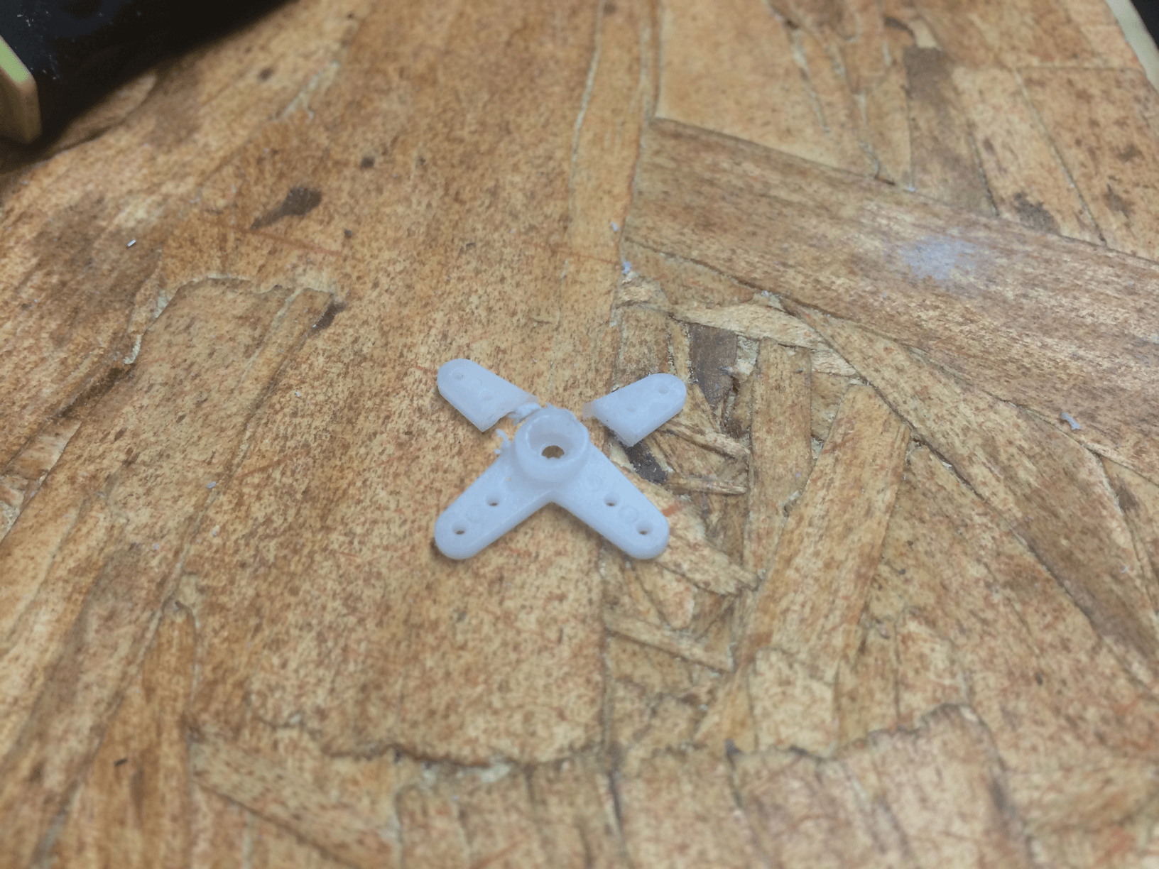
Like so
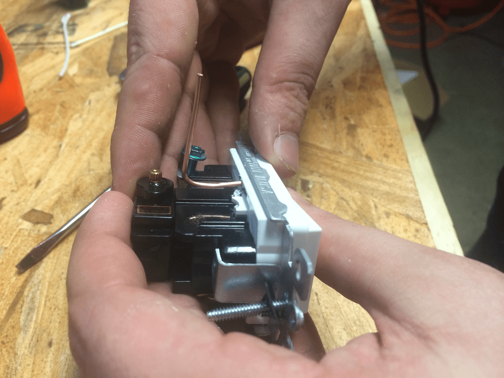
It should look like this once it is attached
Shape the wire so that it can easily be toggled by the servo.
Yet does not protude out to far past the lightswitch body
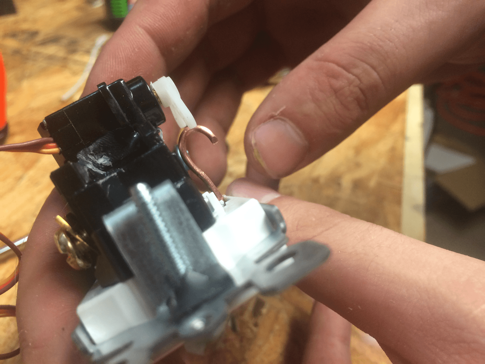
The mechanical portion is complete!
Stay tuned for the circuit and firmware!
coming soon.
EDIT:
I just realized I never linked in the videos of it in action, bear in mind these are of the first prototype where the servo was connected to the toggle mechanically, the version outlined in this blog post is superior as there is no mechanical linkage to break.
Where is the circuit and code. This is so cool
Thank you for the great idea! works well and is inexpensive!
It would be great if you could post your code example. Thanks for this, it’s going to make my setup much more resilient considering human input and digital can be combined to eliminate the need for neutral wires got switching remotely.
This seemed like a great idea so I got the parts and put one together on the bench, worked great except I have my doubts about using hot glue to hold the server on. I had knocked it off twice so used superglue instead. Anyway, when it came to putting the switch into an actual wall box that’s where its downfall became apparent. There just isn’t the room to be able to fit the switch with the servo into the box with the wires. Maybe a single switch in a double gang box would be ok but that wouldn’t work for me.
Maybe if it was an open backed box, or if more of the wires could be shoved into the wall cavity maybe it would work but I had to call it quits.
So, for others reading this site, I’d suggest checking out your wall boxes first, see if there’s enough space in there.
Thanks for the post though, an interesting idea that might work in some homes.
Super glue is probably a much better bet, and I ran into the same issue with depth. The biggest hangup that I ran into is that it is almost impossible to get a 120v ac to 5v dc module that will also fit back there aswell. Only reason I posted it was I had never seen anyone do it, hoped it could inspire someone to make something better.
What about crack open an usb adapter ?
That was the plan, but there is really not a ton of space in these outlets :/ also there is some US Electrical code that says no to high and low voltage in the same enclosure
No video of it in action? Boo!
That is extremely cool, I will probably try and make one of those just for fun, though I see you’ve realized that it won’t fit in a box and it violates a bunch of electrical codes… Codes be damned though, dremel a hole in the back of the box and run your pull wires out of the box and then you won’t have HV/LV in the same box 😛
Hey thanks for visiting! I updated the post, never realized I didn’t link in the videos thanks! They are there now. But they are of my v1 prototype where the servo was directly connected to the light switch, this one outlined in the build process is better, you just have to remember to move the servo back to a neutral position after toggling on or off.
OK, I just made one of these but I did it in a “safe” way…. I have a Leviton decora switch PN 5601, under the paddle there are holes drilled all the way trhough the body of the switch to the ground plate… I hot glued some fishing line to the back side of the paddle and ran it through the existing holes (I did not cut, drill or modify the switch in any way other than adding some non conductive fishing line and hot glue… Now I can pull the wires to turn the switch on and off… You could in theory make 2 tiny holes in the back of a plastic box and mount the servo on the back of the box. The holes wouldn’t be big enough for fingers or for wires to pop out and the low voltage stuf fwould be outside the box so you wouldn’t have to worry about space or breaking the LV / HV in the same box code…
I might actually hook a servo up to this later on and try and make it go… Will check out your videos in a few mins!
That’s an interesting idea, if you do go that route i would probably use one of the strait line servo horns and leave slack on both lines so don’t move the servo when toggling manually, and then also always return the servo to a neutral position in between toggle events
I actually glued a servo to the back to the switch for now, getting the slack right was tough but I can turn the servo and get it to toggle and I can flip the switch manually without forcing the servo… I don’t have a spare micro right now so I can’t really drive the servo and I don’t really want to pull apart one of my finished projects when one should be coming in the mail any day now.. When it shows up I’ll write up a little code to toggle it and make a video… I don’t have any fishing line handy but I used some breadboard connector wires for POC since this isn’t going in a real wall switch… YET 😛 I might use this “technology” on my LV 3-way stick up switch thing… I’m pretty sure it would be safe though with non conductive wires and not modifying the body of the switch in any way other than adding a little hot glue to the rocker… Anyway I’ll post again when I’ve got more to show…
https://www.youtube.com/watch?v=BXbQ4DRkqv0
How does it handle manual toggles?
As long asn it’s not actively running on the servo, the servo goes back to neutral position… There is enough slack on either wire that manual toggles don’t affect the servo…
I also asked an electrician friend if making a tiny hole in the back of a box was against code here in Canada and apparently it’s not if it’s smaller than 1/4″
He also said if it didn’t partially toggle the switch and cause arcing it shouldn’t start a fire or be dangerous but he figured if there was a fire I would have some questions to answer… He couldn’t reccomend installing it, but from what I understand it’s not technically breaking any codes with non conductive lines and the servo on the back side outside the box…
I don’t really have anywhere good to install it though so it probably won’t be seeing mains voltage.
haha yeah the fear of finger pointing after a fire is real, I ordered some of these, haven’t tested them yet, but they are cheap and have ESP8266’s in them, seem like a good bet